9. Poppy humanoid: wiring arrangement
9.1. Data and power buses
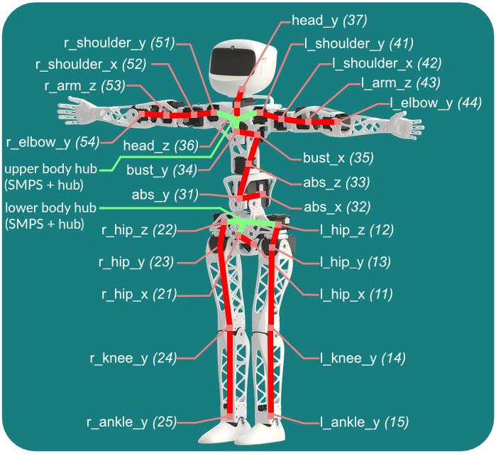
Before you can startup your robot, let's have a look at the cables. You must connect wires from motors to motors by forming 2 different buses:
- Upper body (from
head_ytoabs_x) - Lower body (from
r_hip_zandl_hip_ztor_ankle_yandl_ankle_y)
These 2 buses are fully disconnected from each other (1), they have their own:
- Power supply (SMPS2Dynamixel + wall socket)
- Dynamixel hub to plug up to 6x motors
- USB2AX
The drawing below shows the 2 data and power buses: cables connecting motors are in red, data hubs and SMPS power injection in green.
(1) N.B.: If you own a single power supply unit, you may connect both power buses together by adding a 4-wire cable and cutting out its data bus so that only 1 SMPS2Dynamixel is powered, as shown in the video. But this is unnecessary in most cases since robots are sold with 2 power supply units.
Both USB2AX adapters have to be plugged to the USB sockets of the Raspi3 at the bottom of the head. If you mess up with wiring, at first startup, software will report missing motors or too much motors or the same bus.

9.2. Power supplies for Poppy Humanoid
The robot requires 3 power supply cables:
- 12V power supply for the SMPS2Dynamixel of the upper body
- 12V power supply for the SMPS2Dynamixel of the lower body
- 5V micro USB power supply for the Raspberry Pi 3
For now you can plug the 3 cables to the robot but wait a bit before connecting them to the wall socket. Indeed, there's a few things we need to setup before we can start the software.
9.3. Connect to the robot
Let's getting started with software! Please checkout the dedicated section: Getting started with Poppy software. Psst, before you leave: don't forget to fasten the last screws to fix your head face after you got it working from software.